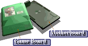
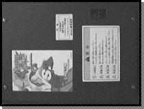
The main CPS-2 motherboard (known as the 'A board') is distinguished by the color found on the
main test and volume buttons. The color codes match those used by the game boards as listed a little later.
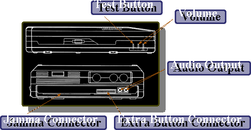
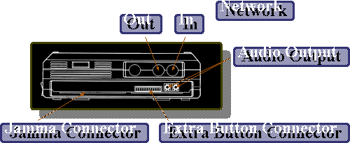
The motherboard has several outputs in various locations.
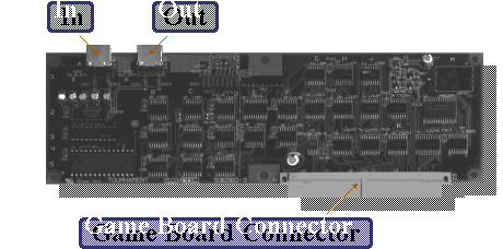
The CPS-2 Game board (known as the 'B board') comes in five different colors. It was thought that these colors matched up to the language used in game but
on getting all the different colored 'A' boards it's clear to see that the color donates the country of release.
| Green : |
Japan |
| Blue : |
U.S.A. and Europe |
| Orange : |
South America |
| Grey : |
Asia |
| Yellow : |
All (Rent version) |
Grey and Orange game boards require the main 'A' board of matching color to work. Green and Blue boards are totally interchangeable meaning Green game boards will work on a Blue 'A' board and visa versa.
A Yellow case shows a game is the rent version. These were made to fit 'A' boards as required and were used to entice operators to buy the game.
Before we start going into any real detail regarding the CPS-2 system here are the general machine specifications.
| Main Processor : |
Custom 68000 at 12 Mhz |
| Address Bus : |
24 bit |
| Data Bus : |
16 bit |
| |
| Sound Processor : |
Zilog Z80 at 8 Mhz |
| |
| Sound Channels : |
16 Stereo Channels |
| Sound Format : |
PCM QSound |
| |
| Color Palette : |
32 bit |
| Total On Screen Colors: |
4096 |
| Colors per tile : |
16 (4 bits per pixel) |
| Object Number : |
900 (16 x 16 pixels) |
| Scroll Faces : |
3 |
| Resolution : |
384 x 224 |
| |
| Maximum Capacity : |
322 Megabits |
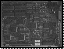
Ok so far so good. Now that we have seen the outside of the unit
and have some basic information, lets open her up and take a closer look the the motherboard
itself.
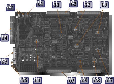
| 01 : |
Test Button |
02 : |
Volume Up / Down |
| 03 : |
Game Board Connectors |
04 : |
JAMMA Connector |
| 05 : |
Extra Button Connector |
06 : |
Audio Output (RCA) |
| 07 : |
Gate Array |
08 : |
DRAM Refresh Controller |
| 09 : |
S-RAM |
10 : |
I/O Line Controller |
| 11 : |
Z80 Processor |
12 : |
Qsound Digital Processor |
| 13 : |
Graphics Processors |
|
|
JAMMA (Japanese Arcade Machine Manufacturers Association) is a universal
connector used to attach games to arcade cabinets. The extra button connector is needed
as the JAMMA connector used with CPS-2 only allows for three buttons per player when most fighting
games need six.
Here are the pin outs of the JAMMA and Extra Button Connector.
JAMMA connector
SOLDER SIDE |
# |
# |
PART SIDE |
GND | A | 01 | GND |
GND | B | 02 | GND |
+5V | C | 03 | +5V |
+5V | D | 04 | +5V |
NC | E | 05 | NC |
+12V | F | 06 | +12V |
| H | 07 | |
NC | J | 08 | Coin Counter 1 |
Coin Lockout | K | 09 | Coin Lockout |
Loudspeaker (-) | L | 10 | Loudspeaker (+) |
NC | M | 11 | NC |
Video Analog Green | N | 12 | Video Analog Red |
Video Composite Sync | P | 13 | Video Analog Blue |
Service Switch | R | 14 | Video Ground |
NC | S | 15 | Test |
Coin B | T | 16 | Coin A |
Player 2 Start | U | 17 | Player 1 Start |
Player 2 Up | V | 18 | Player 1 Up |
Player 2 Down | W | 19 | Player 1 Down |
Player 2 Left | X | 20 | Player 1 Left |
Player 2 Right | Y | 21 | Player 1 Right |
Player 2 Button 1 | Z | 22 | Player 1 Button 1 |
Player 2 Button 2 | a | 23 | Player 1 Button 2 |
Player 2 Button 3 | b | 24 | Player 1 Button 3 |
Player 2 Button 4 | c | 25 | Player 1 Button 4 |
NC | d | 26 | NC |
GND | e | 27 | GND |
GND | f | 28 | GND |
|
EXTRA BUTTON Connector
BOTTOM |
# |
# |
TOP |
GND | 02 | 01 | GND |
+5v | 04 | 03 | +5v |
+12V | 06 | 05 | +12V |
Configurable | 08 | 07 | Configurable |
Configurable | 10 | 09 | Configurable |
Configurable | 12 | 11 | Configurable |
Configurable | 14 | 13 | Configurable |
Configurable | 16 | 15 | Configurable |
Configurable | 18 | 17 | Configurable |
Configurable | 20 | 19 | Configurable |
Configurable | 22 | 21 | Configurable |
Configurable | 24 | 23 | Configurable |
Configurable | 26 | 25 | Configurable |
Configurable | 28 | 27 | Configurable |
Volume Down | 30 | 29 | Volume UP |
| 32 | 31 | Common Volume |
Common Player 1 | 34 | 33 | Common Player 2 |
Pins 07 to 28 can be configurable to anything as games require. This includes coin inputs, coin lockouts, joysticks and buttons.
On the JAMMA connector H / 07 is the Key Pin which stops the connector being joined the wrong way around. NC = Not Connected.
|
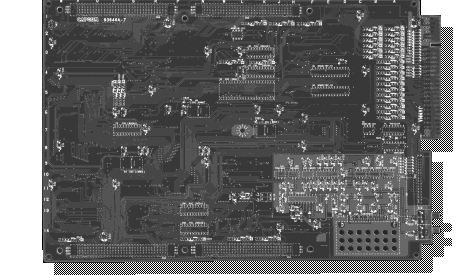
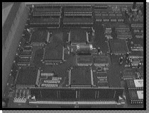
Although there is not allot to see on the solder side of the motherboard we have included
a picture here so you get an 'all round' feel of how it looks.
Well that about covers the main information available on the motherboard at this time.
If you would like to take a closer look at the motherboard above, we have full size scans available for download from the following links.
These are very large files, so be warned.
Motherboard PCB part side (1,216kb)
Motherboard PCB solder side (1,899kb)
The Link Kit
There is only one true link kit for the CPS-2 unit and that is for Super Street Fighter 2 : The Tournament Battle. It works by
assigning each CPS-2 board an ID number on a network and then enables multi-player games on up to four linked cabinets. Look below for a picture of the connections.
The adapter is connected to the game PCB and not the motherboard. Here are some pictures of the adapter starting with the part side.
If you want to take a closer look at the network PCB you can download scans including a picture of the cable connections below.
Network PCB part and solder side (2,186kb)
The Link Cable
Several manuals such as Dungeons & Dragons talk of a link cable for use with 2 cabinets. With this cable only one CPS-2 'A' & 'B' board is needed for the process.
The cable itself contains about 30 wires and some not so easily found hardware, it's simply a JAMMA harness splitter. It routes video, sound and external
wiring to the JAMMA connector on the second cabinet. This Link cable (CAPCOM Part number C-00253) may be obtained through a Coin-OP distributor only but it
may be a discontinued part. If you have any info on this part or diagrams on how to build one please let us know.
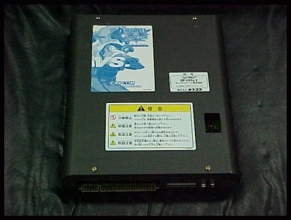
Single Black CPS-2 Unit
As said at the beginning not allot is currently know about the unit except the fact it's an 'A' & 'B' board wrapped into one.
Here are a few more pictures of the board including inside.
 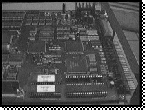
Although these pictures arn't great they do tell us some about the system including the following differences over the standard 'A' & 'B' board setup.
- There is only one PCB and not two sandwiched together.
- The program code is stored on a single simm.
- Graphics and sound data is stored on EPROM's and is in the same format as the standard 'B' board system.
Now for some more pictures, this time more close up splitting the board into four sections with all the main chips pointed out for you.
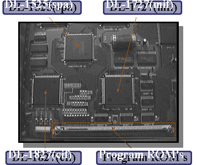
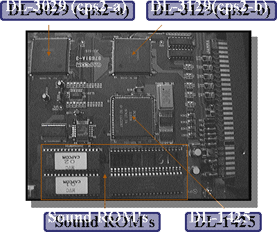
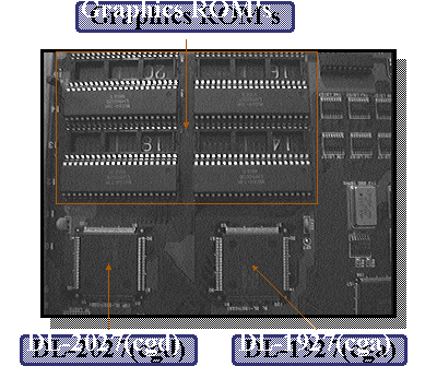
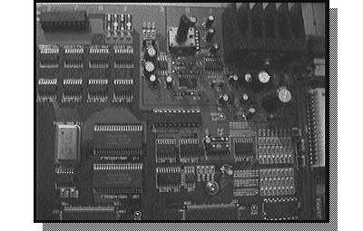
The last section of this PCB doesn't have any custom chips on it but the picture is included for good measure.
Once more is known we will let you know.
If you know any CPS-2 technical info that is not on this page please email
us at techinfo@cps2shock.com so we can keep this page accurate.
|