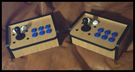
This section contains information and the parts needed to make the joysticks pictured
above. There is no wiring information on this page as these joysticks can be wired in
many different ways to suit your needs.
|
SECTION 1, parts needed.
| |
The arcade parts can be brought from Happ Controls in the states, they also have online ordering.
Here is the list the parts needed and links to Happ Controls to see them.
A shipping fee will be added depending on where you live and type of courier used, you may
also need to pay a customs fee when the package arrives if you live abroad.
The only other parts needed can be found at your local timber merchant, you will need the following;
Heavy Wood, 52cm x 72cm. Must be 16.5mm thick.
8 flat ended nuts & bolts, 40mm x 5mm diameter.
Screws, 25mm length x 4mm diameter.
Black Insulation Tape 2cm wide.
Good Wood Glue.
| |
| |
|
|
SECTION 2, general notes.
| |
Before you start just read through the following pointers to help you understand the diagrams and limit mistakes.
- Be sure to have general carpentry tools handy.
- All measurements are in centimeters and colored yellow in the diagrams, drill points are green.
- All pencil markings are in grey, don't use a pen to mark wood as erasing it later will be difficult.
- Make sure you calculate new dimensions correctly if you are using different parts or thicker wood.
- Do everything in the order shown for ease.
| |
| |
|
|
STEP 1, cutting the wood into sizes needed.
| |
The best way to cut out the wood is as shown below with the grain running from the top of the wood to the bottom.
Once cut label the wood pieces to the names in grey.
Take the four pieces labeled 'side' and using the outside edge of a blank ID tags mark around the
outer circle to round off one corner. If you did not get the parts as listed the radius is 18mm, look below if you are stuck.
Remove that corner on each of the four pieces to leave one corner round, once done pieces will look like this.
Now do the same with the two pieces labeled 'top' but this time remove two corners which are length opposite.
When finished the two pieces will look like this.
All that is left to do now is to separate all the wood into two piles, that's one pile for each joystick.
| |
| |
|
|
STEP 2, lining up pieces & general markers.
| |
Using one pile of wood only, place the pieces as shown in the diagram below on a flat surface. The piece labeled 'top' is not needed at this point.
Now lift and turn all 4 outer pieces inwards by 90 degrees to make sides around the piece labeled 'bottom', look at the next diagram if you not sure what I mean.
At this point make sure everything fits together flush, if not sand or plain the wood in question until it does.
Now draw around all the inside edges and lay the four pieces back down, it will look like this diagram once done.
Now turn both side pieces so they match against the back piece flush. Bottom & front pieces are no longer needed at this point,
look at the next diagram if your not sure.
Draw a straight line across all three pieces using the lines that show where the front piece sat as pointers. Draw another line
16.5mm above that, this leaves the three pieces looking like the diagram below.
Once finished repeat this step on the other pile of wood you have. Make sure you do to mix wood between piles as this could lead to
wood not fitting correctly later.
| |
| |
|
|
STEP 3, drilling and building.
| |
Look carefully at the next three diagrams.
The green crosses need to be drilled through with a 4mm diameter drill bit (use the correct
size for the screws your using). Make sure to drill in the middle of the grey lines and
edges, being one sided can cause wood to split later.
Once you have drilled the necessary wood in both piles you can start to assemble. First lay the
pieces from one pile out as shown below on a flat surface and glue in the places marked orange, do not put glue in the drill holes.
Now assemble the pieces as we did before making any adjustments to get everything flush. Do the same with both piles of wood and once done leave to dry.
When dry use screws to tighten it all together by first putting a little glue in a drill hole, then use a screw and tighten. This will give extra strength
to your joystick.
| |
| |
|
|
STEP 4, adding the top.
| |
First make sure the piece labeled 'top' fits as it should,
if not sand or plain the wood until it does. Look at the next diagram to see how it fits, outlined orange.
Now It's time to mark where all the buttons & stick go, remember if you are using different parts measurements may change. The layout I chose is below
though you can change it if required to suit your needs.
Once you have marked out all nine drill points you can use a 30mm diameter drill bit to make the holes. Some of you won't have this so use a compass to outline each hole
with a radius of 15mm. Use the biggest drill bit you can and make as many holes inside each circle as you can, then use a jigsaw, hacksaw, file or hammer & chisel to remove the rest.
Once done make sure the buttons fit into all the holes, even the hole used by the joystick.
Take the piece of joystick that's going to be hidden on the inside of the case and center it up over the hole its to be fitted under. Make sure joystick casing is
lined up long ways if its not square and once centered mark out the four holes already in the casing, look below.
Finally remove the joystick away and drill the four holes through with a 5mm drill bit. Once finished repeat step four with the other top piece.
| |
| |
|
|
STEP 5, final assembly.
| |
The first thing you need to do is print out the following diagram to its actual size, this is for the ID tags.
Once the print is dry use one ID tag as a template to cut around the shapes and center circles of your print.
Now attach the parts to both the top boards, everything goes in the following places if you can't work it out.
Now is the time to add your wiring, I suggest the I-PAC interface if you intend PC use.
You will also need to drill a hole in the back of the case to allow your wiring to exit. Once done you can attach the top pieces to their boxes.
Don't use glue as this is the way to open the box if parts break in the future.
Screw in the final screws to hold it all together and now your almost finished.
Now go around the entire boxes erasing any pencil marks that show, this leaves the final job which is adding the black tape.
Basically cover all places where the wood thickness shows, once on carefully slice off with a sharp knife any overhanging tape.
That's it, job finished. The end result will look something like the two sticks below unless you did a total rush job.
| |
| |
|
|
|


|