|
STEP 1, cutting the wood into sizes needed.
| |
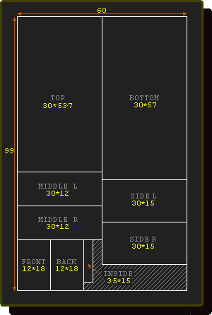
The best way to cut out the wood is as shown below with the grain running from the top of the wood to the bottom.
Once cut label the wood pieces to the names in grey.
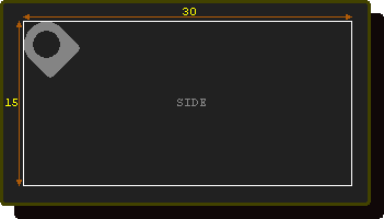
Take the two pieces labeled 'side' and using the outside edge of a blank ID tags mark around the
outer circle to round off one corner. If you did not get the parts as listed the radius is 18mm, look below if you are stuck.
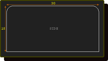
Remove that corner and its length opposite corner on both pieces, once done both pieces will look like this.
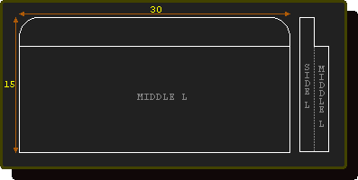
Lastly glue the piece labeled 'middle l' to the piece labeled 'side l' as the diagram below shows. Do
not glue the pieces 'middle r' and 'side r' together.
| |
| |
|
|
STEP 2, drilling & semi assembly
| |
Look carefully at the next five diagrams.
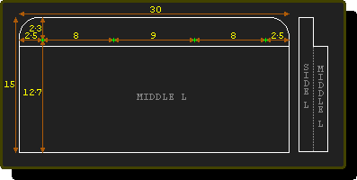
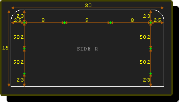
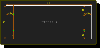
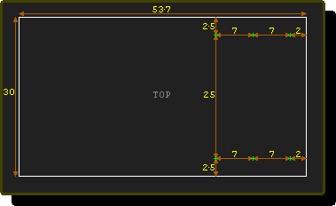
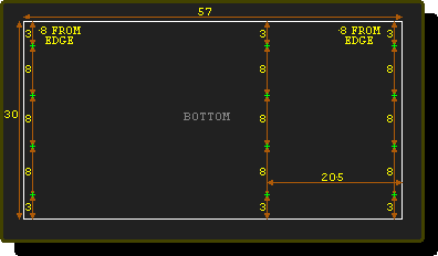
All the green crosses need to be drilled through with a 4mm diameter drill bit. Once the five pieces are done look at the diagram
below and assemble the wood as shown with the screw holes in the top piece to the right side, not the left. Do not fasten any wood together yet.
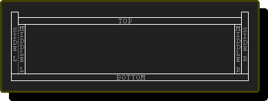
Make sure everything fits together flush, if not sand or plain the wood in question until it does.
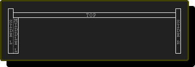
Now you can join 'side / middle l' and 'side r' to the top piece using screws and glue, don't join 'middle r' and 'bottom'
as these will be joined later on. You will be left with the following.
| |
| |
|
|
STEP 3, adding parts & assembly.
| |
Take the pieces labeled 'front' and 'back' and make sure they fit correctly.
If they don't sand or plain them until they do. Look at the next diagram to see how it should all fit together,
pieces in question are outlined orange with the back piece behind the front piece.
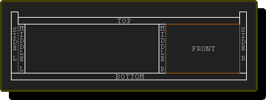
Now It's time to mark where all the buttons etc go, remember if you are using different parts measurements may change. The layout I chose is below
though you can change it if required to suit your needs.
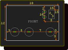
Once you have marked out the drill points you can use a 30mm diameter drill bit to make the three button holes and a 12mm diameter bit to make the two fuse holes. If you don't have a 30mm diameter drill bit use a compass to outline the three
button holes with a radius of 15mm. Use the biggest drill bit you can and make as many holes inside each circle as you can, then use a jigsaw, hacksaw, file or hammer & chisel to remove the rest. Do the same with the 3cm x 2cm rectangle hole for the
on / off switch. Once done make sure everything fits into it's hole.
The next thing you need to do is print out the following diagram to its actual size, this is for the ID tags.
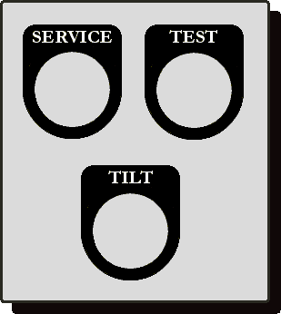
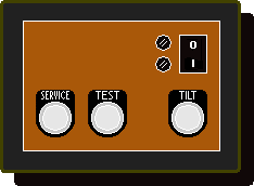
Once the print is dry use one ID tag as a template to cut around the shapes and center circles of your print. Now you can attach all the parts where they belong on the front piece,
once done it will look like this.
Next take the piece of wood marked 'back' and mark out the following within it.
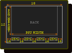
Now take great care and remove the insides of the four rectangles and of the large square. The aim is to get
the power supply to slot inside the space tightly, the 15 pin D-TYPE female connectors should also fit into the four spaces neatly.
Cover the remaining wood on one side with black tape and trim to leave the spaces, this will show on the outside. You will be left with the following.
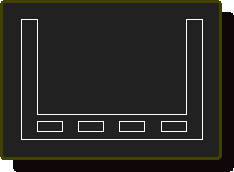
Next take the piece of wood marked 'middle r' and mark out the following within it.
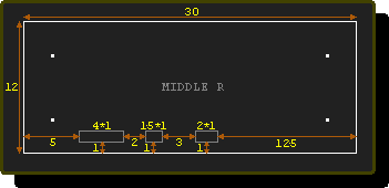
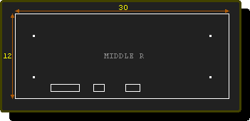
Again take great care and remove the insides of the three rectangles until the 25 and 9 pin D-TYPE female connectors fit into their two spaces neatly.
The third space (right) allows wiring to exit to the 56 pin edge connector. Once finished you will have the following.
Finally take the power supply and all your pieces except 'bottom' and arrange them as they should be assembled.
Look below to see how, there are two different views to make it easier to understand.
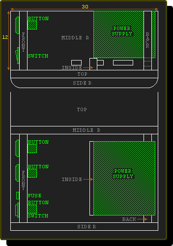
The aim is to make sure the top of the power supply runs parallel to the top of 'middle r' and 'side r ' at an equal height.
If it does not make adjustments to the pieces 'inside' and 'back' until it does.
Once done you can assemble these pieces using glue and screws in all the holes you drilled earlier. It's best to glue it all first and
allow to dry before adding the screws. Be careful with the back piece as it can easily split,
I advise keeping the power supply in place while attaching it. Also file away the tip of any screw that appears in the four
holes under the power supply. The inside piece just needs to be glued into place but you will need to put a couple of screws halfway into its top,
this will stop the power supply moving towards the buttons once assembled.
| |
| |
|
|
STEP 5, wiring and final assembly..
| |
First take a look at all the pins and what they do.
JAMMA connector
SOLDER SIDE |
# |
# |
PART SIDE |
GND | A | 01 | GND |
GND | B | 02 | GND |
+5V | C | 03 | +5V |
+5V | D | 04 | +5V |
-5V | E | 05 | -5V |
+12V | F | 06 | +12V |
| H | 07 | |
Not Connected | J | 08 | Coin Counter 1 |
Coin Lockout | K | 09 | Coin Lockout |
Loudspeaker (-) | L | 10 | Loudspeaker (+) |
Not Connected | M | 11 | Not Connected |
Video Analog Green | N | 12 | Video Analog Red |
Video Composite Sync | P | 13 | Video Analog Blue |
Service Switch | R | 14 | Video Ground |
Tilt | S | 15 | Test |
Player 2 Coin | T | 16 | Player 1 Coin |
Player 2 Start | U | 17 | Player 1 Start |
Player 2 Up | V | 18 | Player 1 Up |
Player 2 Down | W | 19 | Player 1 Down |
Player 2 Left | X | 20 | Player 1 Left |
Player 2 Right | Y | 21 | Player 1 Right |
Player 2 Button 1 | Z | 22 | Player 1 Button 1 |
Player 2 Button 2 | a | 23 | Player 1 Button 2 |
Player 2 Button 3 | b | 24 | Player 1 Button 3 |
Player 2 Button 4 | c | 25 | Player 1 Button 4 |
Not Connected | d | 26 | Not Connected |
GND | e | 27 | GND |
GND | f | 28 | GND |
Extra Button Connector
| PIN |
DEVICE |
01 | 1up Action Button 4 |
02 | 1up Action Button 5 |
03 | 1up Action Button 6 |
04 | 2up Action Button 4 |
05 | 2up Action Button 5 |
06 | 2up Action Button 6 |
07 | Not Connected |
08 | Volume Up |
09 | Volume Down |
|
3 & 4 Player In
| PIN |
DEVICE |
01 | 3up Action Button 1 |
02 | 3up Action Button 2 |
03 | 3up Action Button 3 |
04 | 3up Action Button 4 |
05 | 3up Action Button 5 |
06 | 3up Action Button 6 |
07 | 3up Insert Coin Button |
08 | 3up Start Button |
09 | 3up Joystick Up |
10 | 3up Joystick Down |
11 | 3up Joystick Left |
12 | 3up Joystick Right |
13 | Not Connected |
14 | 4up Action Button 1 |
15 | 4up Action Button 2 |
16 | 4up Action Button 3 |
17 | 4up Action Button 4 |
18 | 4up Action Button 5 |
19 | 4up Action Button 6 |
20 | 4up Insert Coin Button |
21 | 4up Start Button |
22 | 4up Joystick Up |
23 | 4up Joystick Down |
24 | 4up Joystick Left |
25 | 4up Joystick Right |
Joystick Out
| PIN |
DEVICE |
01 | Action Button 1 |
02 | Action Button 2 |
03 | Action Button 3 |
04 | Action Button 4 |
05 | Action Button 5 |
06 | Action Button 6 |
07 | Insert Coin Button |
08 | Start Button |
09 | Joystick Up |
10 | Joystick Down |
11 | Joystick Left |
12 | Joystick Right |
13 | Not Connected |
14 | Not Connected |
15 | Ground (common) |
|
It's now just a case of connecting all the wires to their correct place and using heat shrink to protect and stop
interference, especially to the video signals. Allow wire to exit it's hole in 'middle r' by about about 50cm before connecting to the 56 pin JAMMA connector.
Once all the wiring is done I suggest you check everything with a multimeter if you have one. Once done you can finally attach the 'bottom' piece
of wood and your finished. Ok now lets start with the power and ground wiring.
Power and Ground
First Take a red wire (+5) from the AT power supply and solder it to one of the fuse holders, then from that fuse holder
to the following 4 pins on the JAMMA connector.
C, 03, D ,04
Next take a yellow wire (+12) and solder it to the other fuse holder, then from that fuse holder
to the following 2 pins on the JAMMA connector.
F, 06
Now take a white wire (-5) and solder it to the following 2 pins on the JAMMA connector.
E, 05
Finally take a black wire (ground) and solder it to the following 8 pins on the JAMMA connector.
A, 01, B, 02, e, 27, f, 28
The black ground also needs to go to pin 15 on all four joystick out connectors and to each common point on
the three buttons. This can be done in a serial manor.
Finally use a 10amp fuse to protect the +5v line and a 2amp fuse to protect the +12v line by inserting them into
the fuse holders.
3 & 4 Player Connections
This is very straight forward. Connect all the player 3 and 4 pins from the 3 & 4 player input to two of the
four joystick out connectors, 3up to one and 4up to the other. Look above to see which pins are which. For example pin 20 of the 3 & 4 player
in goes to pin 07 on a joystick out.
1 & 2 Player / Extra Button Connections
Again this is very straight forward. Connect all the player 1 and 2 pins from the JAMMA connector and the extra button connector to the last two
joystick out connectors, 1up to one and 2up to the other. Look above to see which pins are which. Note that button 4 comes from both JAMMA and extra button
connectors, they must both the soldered to the same pin (4) on the joystick outs.
Other Buttons
I'm sure if you have got this far you can work this out. Remember to connect to the points labeled 'N.O.' or 'Normally Open' on the buttons micro switches.
Pin R from the JAMMA to the Service Button
Pin S from the JAMMA to the Tilt Button
Pin 15 from the JAMMA to the Test Button
Audio
My JAMMA rig does not have a built in speaker at this point so I have not used the JAMMA speaker output. The CPS-2 A Board has RCA outputs
which I have wired up to a set of PC speakers for sound. If your going to add a speaker to your unit connect
the following pins to it.
Pin L from the JAMMA to Speaker -
Pin 10 from the JAMMA to Speaker +
Video
This is the only part that you could get stuck on as there are many ways to connect the video to different
devices. I used an Amiga 1084s monitor which wires as follows.
Connector = 6 PIN DIN MALE
Pin 12 from the JAMMA to Pin 4
Pin N from the JAMMA to Pin 1
Pin 13 from the JAMMA to Pin 5
Pin P from the JAMMA to Pin 6
Pin 14 from the JAMMA to Pin 3
If you have an Amiga 1084st monitor it wires as follows.
Connector = 9 PIN D TYPE
Pin 12 from the JAMMA to Pin 3
Pin N from the JAMMA to Pin 4
Pin 13 from the JAMMA to Pin 5
Pin P from the JAMMA to Pin 7
Pin 14 from the JAMMA to Pin 1 and 2
For a TV with a SCART socket you can wire a lead that will plug directly into your TV as follows.
Connector = SCART (male)
Pin 12 from the JAMMA to Pin 15
Pin N from the JAMMA to Pin 11
Pin 13 from the JAMMA to Pin 7
Pin P from the JAMMA to Pin 20
Pin 14 from the JAMMA to Pin 17, 13, 9 and 5
+5v from PSU to Pin 16 via a 100ohm resistor
If you want to wire to a female SCART connector and then connect to a TV via a ready made SCART lead
(male connector at both ends) then use the following.
Connector = SCART (female)
Pin 12 from the JAMMA to Pin 15
Pin N from the JAMMA to Pin 11
Pin 13 from the JAMMA to Pin 7
Pin P from the JAMMA to Pin 19
Pin 14 from the JAMMA to Pin 17, 13, 9 and 5
+5v from PSU to Pin 16 via a 100ohm resistor
With any monitor using RGB inputs (not a PC VGA monitor) it's normally a simple case of connecting up the RGB,
Video Sync and Video Ground and it should work. If the monitor uses separate horizontal and vertical sync try connecting the
video sync to the vertical sync only, sometimes this works. If not you will need to buy a IC that can extract both signals from the
video sync.
| |
| |
|
Return to the JAMMA Building Page
|
|


|


